

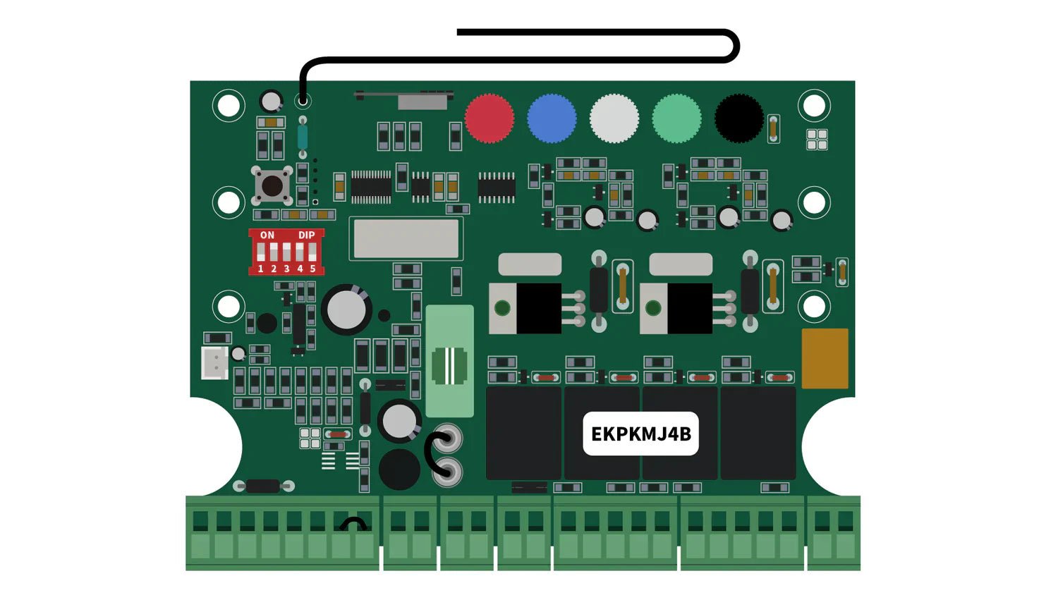
Knowing the function of each terminal on the control board of your gate operator is essential to avoid confusion, prevent damage, and ensure a successful setup. This guide explains the key terminal functions using the RITROX / LOCKMASTER RXD365, EKD365, and EKD700 swing gate openers, specifically the EKPKMJ4B control board as an example.

📋 Terminal Overview
| Terminal | Label | Description |
|---|---|---|
| 1 | +24 | 24VDC Output |
| 2 | PHOTO | Photocell Input |
| 3 | GND | Ground |
| 4 | O/S/C | Open/Stop/Close |
| 5 | COM | Common Terminal |
| 6 | OPSW | Open Switch |
| 7 | EDGE | Edge Sensor |
| 8 | GND | Ground |
| 9–10 | ADAPTER | AC/DC Adapter Input |
| 11–12 | +BAT- | Battery Input |
| 13–14 | -LOCK+ | Electric Lock Output |
| 15–16 | MOTOR1 | Motor 1 Connection |
| 17 | ULT1 | Up Limit Switch 1 |
| 18 | COM | Common Terminal |
| 19 | DLT1 | Down Limit Switch 1 |
| 20–21 | MOTOR2 | Motor 2 Connection |
| 22 | ULT2 | Up Limit Switch 2 |
| 23 | COM | Common Terminal |
| 24 | DLT2 | Down Limit Switch 2 |
| 25–26 | +LAMP- | Alarm Light Output |
Note: Terminals are typically used in pairs and not individually. Accessories often require multiple terminal connections.
🔌 Functional Descriptions
Terminals 1 (+24) & 3 (GND)
-
Function: Provides 24VDC output to power photocells or sensors.
-
Note: Output is only active when the motor is running. Compatible with third-party photocells.
Terminals 2 (PHOTO) & 3 (GND)
-
Function: Signal input from the photocell. Operates on Normally Closed (NC) contact.
-
Behavior: When the sensor is blocked, the gate stops or reverses. Compatible with third-party NC dry contact photocells.
Terminals 4 (O/S/C) & 5 (COM)
-
Function: Trigger gate operation (Open → Stop → Close) using Normally Open (NO) dry contact.
-
Usage: Connect wall switches, keypads, or external receivers.
Terminals 6 (OPSW) & 5 (COM)
-
Function: Trigger gate opening only. Typically used with a vehicle sensor or loop detector (NO dry contact).
-
Behavior: When a vehicle is detected, the gate opens. It does not close or stop.
Terminals 7 (EDGE) & 8 (GND)
-
Function: Input from an edge safety sensor (e.g., rubber safety edge).
-
Behavior: If the gate hits an obstacle, the signal opens and the gate retracts. Works on Normally Closed input.
Terminals 9–10 (ADAPTER)
-
Function: Input for a power adapter to charge the battery. Accepts 36VDC or 24VAC.
Terminals 11–12 (+BAT-)
-
Function: Main 24VDC power input from battery or DC power supply. Powers the entire system and accessories.
-
Note: Compatible with third-party 24VDC 180W adapters.
Terminals 13–14 (-LOCK+)
-
Function: Output for electric gate lock (24VDC for 4 seconds after gate begins to open).
-
Note: Supports locks with 24VDC, max 3A current.
Terminals 15–16 (MOTOR1) / 20–21 (MOTOR2)
-
Function: Connects to Motor 1 and Motor 2 (red and black wires).
Terminals 17 (ULT1), 18 (COM), 19 (DLT1) / 22 (ULT2), 23 (COM), 24 (DLT2)
-
Function: Inputs for limit switches:
-
ULT (Up Limit): For near-limit position
-
DLT (Down Limit): For far-limit position
-
-
Note: Use the green wire as common and connect it to the COM terminal.
Terminals 25–26 (+LAMP-)
-
Function: Output for flashing alarm light during gate operation.
-
Note: 24VDC, max 1A. Compatible with most 24VDC lights.
⚠️ Safety Tips
-
Always turn off the power before making any wiring adjustments.
-
Stay clear of the gate during configuration to avoid injury from unexpected movement.

✅ Conclusion
Each terminal on the EKPKMJ4B control board plays a vital role. By understanding their functions and wiring them correctly, you can maximize the performance, safety, and reliability of your RITROX / LOCKMASTER RXD365, EKD365, or EKD700 swing gate operator.
If you have any questions about wiring or setup, feel free to contact our support team — we’re here to help!

Leave a comment
This site is protected by hCaptcha and the hCaptcha Privacy Policy and Terms of Service apply.